3.2. Regulation and control of water-treatment plant technology (╚OV, CH┌V)
 The term "chemical water-treatment plant" means a set of technological equipment (clarification, sand filtration,
demineralisation with eventual post treatment by mixed-bed filters, regenerative system, chemical dosing, waste water
neutralisation) used in power and heating plants for the production of de-mineralised water to feed boilers and to
produce cooling water. The output of these plants ranges between 50 and 300 m3/hour.
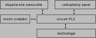
The technology control system is based on the application of programmable logic controllers (further referred to as PLC) with a superior PC with visualising software at the dispatching site. The individual PLCs and PCs are interconnected by communication busbars. According to local conditions and the extent of the technology, the control system is designed centralised or locally decomposed. Locally decomposed configurations using remote input/output units or more PLC's enables clear arrangement of the control system and its easier extension.
The control system processes signals from sensors and analysers of field instrumentation (flow, temperature, pressure, water level, conductivity, concentration, pH, cloudiness, O2 content, SiO2 content, etc.); it makes the required calculation with the measured data and intervenes on the basis of the measured values.
Contact with operators is provided via colour monitor with displayed technological diagrams. The measured values are displayed in technological diagrams directly in places where the sensors are positioned. The diagrams present all the controlled equipment (valves, pumps, compressors, etc.). The individual pieces of equipment work either automatically according to the programmed algorithms or they can be controlled individually and manually from the dispatching site (using so-called mouse and monitor or touch screen) or from the stations located directly in the shop (via control consoles or local control boxes). The monitor at the dispatching site displays the states of the controlled equipment even during local controlling and the dispatcher is always informed of switching over to local mode.
The monitor at the dispatching site and the linked printer are used to print out failure messages, reviews of archived data one year back, reviews of all operator interventions and to display and print out graphs of time behaviour of the selected measured values. The monitor can be used to display a sufficient number of detailed and overview pictures of part of the technology created by request of the technology owner. It is possible to move easily from one picture to another.
The dispatching sites are usually equipped with PCs in industrial versions complete with monitors (currently it is mainly flat LCDs monitors; with large applications even more monitors at one dispatching site), keyboard and a positioning device (mouse, trackball). For the visualisation, various types of SW visualisations are used (i.e. In-Touch, Promotic) according to the extent of the controlled technology.
A useful accessory to the equipment at the despatching site is a large-size panel with a schematic representation of the overall mimic diagram of the technology with the most important technological values displayed. Large-size panel designs range from cost-effective panels with a drawn technology diagram and suitably fitted digital display units to display the measured values, mosaic panels, and panels with projection equipment to panels composed of several LCDs or gas plasma screens.
The control system supply may include the equipment of the dispatching site - control panels and operators' chairs.
The PLCs used for the programmable logic controller level come from various world manufacturers (Siemens, Schneider, ABB, B&R, etc.). The PLC selection is consulted with the client for the reason of uniform HW equipment in the client's plants.
The uninterrupted operation of the control system is secured by backed up supply from UPS of a small power selected for the actual application.
The following figure represents the system structure:


